
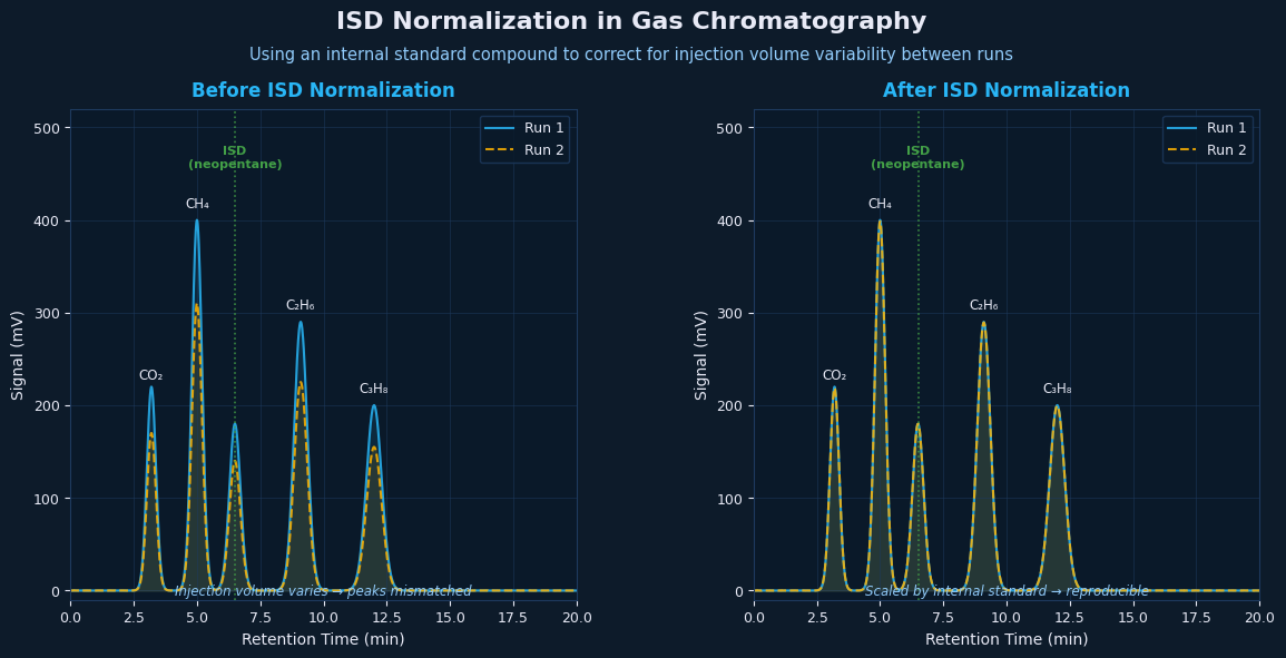
If your GC method uses an internal standard, you have an extra calculation step before you can trust the mole fractions ChemStation reports. Done correctly, it improves accuracy and removes instrument drift from the equation. Done incorrectly — or skipped when it should be applied — it introduces a systematic error that affects every component in the composition.
This article explains what ISD normalization is, how the calculation works, and where it goes wrong in practice.
What Is an Internal Standard?
An internal standard (ISD) is a compound of known concentration that is added to the sample — or to the injection — before the GC run. It serves as an internal reference: by measuring how much of the ISD the GC detects relative to how much was added, you can correct the measured peak areas for anything that affected the injection uniformly.
The key word is uniformly. An internal standard corrects for injection volume variation (gas samples are pressure-sensitive; the exact volume delivered to the column varies slightly from injection to injection) and short-term instrument sensitivity drift. If you injected 5% more gas than nominal, all peak areas will be 5% high — including the ISD. Dividing by the ISD ratio normalizes this out.
An internal standard does not correct for peak integration errors on individual components, co-elution or poor resolution, column contamination that selectively affects certain components, or changes in the sample composition itself.
What Compound Is Used as ISD?
In PVT lab gas analysis, the internal standard needs to be a compound that is not naturally present in reservoir fluids, elutes cleanly without co-eluting with anything in the sample, and is detectable on whichever detector covers its expected response. Common choices include:
Neopentane (2,2-dimethylpropane / isoC₅). Elutes in the C₅ region on most columns, detected by FID. Often used because it’s a pure compound available in certified standard mixtures.
n-Hexane spiked at known concentration into the standard gas. Can be used if it’s absent from the sample fluid type, though this limits applicability to dry gas samples.
Helium, when used as a tracer in injection-recombination studies. In this context it serves a similar normalization role on the TCD channel.
The specific compound matters less than the fact that its concentration and peak response are precisely characterized and consistently applied.
The Normalization Calculation
The ISD normalization is a ratio correction applied to raw peak areas before mole fractions are calculated.
Step 1: Establish the expected ISD response. From a certified standard gas or a prepared mixture, you know the true concentration of the ISD and the peak area the GC should produce for it under standard conditions.
Step 2: Measure the ISD peak area in the sample run. This is the area actually detected for the ISD in the sample injection.
Step 3: Calculate the correction factor. CF = A_ISD,expected / A_ISD,measured. If CF > 1, the ISD gave a smaller signal than expected — the injection was light or detector sensitivity drifted down. If CF < 1, the injection was heavy or sensitivity drifted up.
Step 4: Apply the correction factor to all other peak areas. A_corrected = A_raw × CF. These corrected areas are then used for the mole fraction calculation, and the composition is normalized to 100 mol%.
Where ISD Normalization Goes Wrong
Using the wrong expected ISD value. If the calibration standard has drifted (poor storage conditions, expired certification), or if the expected ISD concentration was entered incorrectly in the method, every correction factor will be systematically wrong — shifted in the same direction for every sample. The error is invisible because the composition still normalizes to 100%.
Misidentifying the ISD peak. On a complex chromatogram, the ISD peak can be confused with a co-eluting sample component. This is particularly a risk when a new column has slightly different retention times, shifting the ISD peak closer to a sample component, or when the ISD concentration is too high, causing detector overload and a distorted peak shape.
Applying ISD correction to only one detector incorrectly. In a dual-detector FID/TCD system, an ISD on the FID channel corrects FID peak areas only. If the FID-derived correction factor is applied to TCD peak areas as well, this is only valid if the TCD and FID sample the same injection volume at the same time — which should be verified against your instrument configuration.
Skipping ISD normalization when the method specifies it. If a lab’s standard procedure requires ISD normalization, skipping it introduces the injection volume variability that the ISD was added to remove. Batch-to-batch precision degrades even if individual runs look correct.
Applying ISD normalization when no ISD was added. The reverse error: if the software applies an ISD correction to a run where no internal standard was injected, the correction factor will be derived from whatever peak happens to fall at the expected ISD retention time — which could be a real sample component. The result is a composition with one component artificially suppressed and all others over-normalized.
ISD Normalization in the Context of the Full Workflow
ISD normalization happens before the FID/TCD merge and before air correction in the processing sequence. The corrected peak areas from each detector are then used as inputs to the merge calculation. The sequence matters:
- Apply ISD correction to raw peak areas (FID and TCD separately)
- Identify and remove air contamination from the corrected TCD table
- Apply FID/TCD merge logic (cross-calibration, detector assignment)
- Normalize to 100 mol%
Applying the steps in the wrong order — for example, normalizing before applying the ISD correction — changes the result. The ISD correction is a scaling of raw areas; it needs to happen before any normalization step collapses the area information.
Verifying the ISD Normalization
A quick sanity check: run a certified standard gas (without ISD spiking) through the GC using your normal method. The resulting composition, after ISD normalization and mole fraction calculation, should match the certificate values within your method’s stated precision — typically within ±0.5 mol% for major components, ±0.1 mol% for trace components.
If the certified standard comes back systematically high or low across all components by the same percentage, that’s a sign the ISD expected value is wrong. If some components are off and others are not, the issue is likely response factors, not the ISD.
Automating ISD Normalization
Like air correction, ISD normalization is a deterministic calculation with a fixed formula and a configurable input (the expected ISD area from your method). There’s no sample-to-sample judgment involved.
GC Reader handles ISD normalization as part of the processing pipeline: you configure the ISD component identity and expected area once per method, and it applies the correction consistently to every sample in a batch before passing the corrected data through the merge and normalization steps.
Also in this series:
- Air Correction in GC Analysis: How to Handle Atmospheric Contamination
- FID/TCD Merge in Gas Chromatography: Why Your Composition Numbers Are Wrong
- Automating GC Composition Reports: From ChemStation to Engineering Software
Related: GC Reader supports liquid GC workflows with ISD normalization, component aliases, and report-ready composition output. See the GC Reader product page.